LCD and button sharing I/O
I often see people struggling to get all the peripheral parts connected up to an Arduino without running out of pins. The thing many people miss, especially early on, is you can connect multiple things to a single pin, so long as you do it right.
In this case we’ll be using an HD44780 alphanumeric LCD, you can run it in 4bit or 8bit mode, with the enable and register select the minimum pin count is 6.

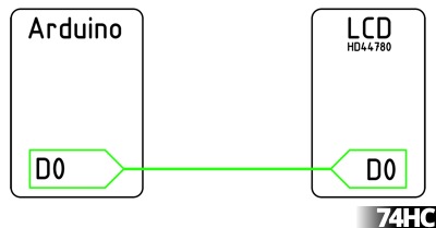
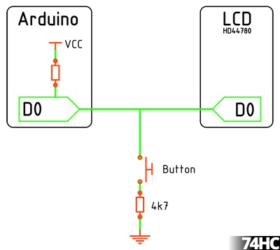
This is maybe what you’re familiar with, a pin on the Arduino connected to one of the bus pins on the LCD, but did you know you can connect a button to the same pin?

The pins on the Arduino can be changed from output to input at any time while the program is running, so our normal pin state is an input with the internal pull-up turned on. The pin will normally read HIGH, when the button is pressed it will pull the pin LOW. When we want to talk to the LCD the pin is set to OUTPUT while the LCD is updated, then reset to the INPUT with pull-up state.
// A function to set the bus to input
void setBus_Input(){
  pinMode(db4, INPUT_PULLUP);
  pinMode(db5, INPUT_PULLUP);
  pinMode(db6, INPUT_PULLUP);
  pinMode(db7, INPUT_PULLUP);
}
// A function to set the bus to output
void setBus_Output(){
  pinMode(db4, OUTPUT);
  pinMode(db5, OUTPUT);
  pinMode(db6, OUTPUT);
  pinMode(db7, OUTPUT);
}
So all we need to do is call the functions when we write to the LCD
setBus_Output();
lcd.print("74HC.co.uk");
setBus_Input();
This is probably a going point to explain the 4k7 pull-down under the button, if the pin state is OUTPUT HIGH while writing to the LCD and the button is pressed, without the 4k7 there would be a dead short. So we fit the 4k7 to stop that, since the internal pull-up is only 20k we still end up with 0.9v on the pin with the button pressed which will be read as LOW just fine.
A complete program will look something like this
#include <LiquidCrystal.h>

// Pin Map, matches Arduino HelloWorld example
const byte lcdEnable = 11
const byte lcdRS = 12;
const byte db4 = 5;
const byte db5 = 4;
const byte db6 = 3;
const byte db7 = 2;

LiquidCrystal lcd(lcdRS, lcdEnable, db4, db5, db6, db7);

void setup(){
  lcd.begin(16, 2);
  lcd.print("74HC.co.uk");
  setBus_Input();
}

void loop(){
  if(digitalRead(db4) == LOW){
    setBus_Output();
    lcd.setCursor(0, 1);
    lcd.print("DB4");
    setBus_Input();
    delay(500);
  }
  else if(digitalRead(db5) == LOW){
    setBus_Output();
    lcd.setCursor(0, 1);
    lcd.print("DB5");
    setBus_Input();
    delay(500);
  }
  else if(digitalRead(db6) == LOW){
    setBus_Output();
    lcd.setCursor(0, 1);
    lcd.print("DB6");
    setBus_Input();
    delay(500);
  }
  else if(digitalRead(db7) == LOW){
    setBus_Output();
    lcd.setCursor(0, 1);
    lcd.print("DB7");
    setBus_Input();
    delay(500);
  }
}

// A function to set the pins to input
void setBus_Input(){
  pinMode(db4, INPUT_PULLUP);
  pinMode(db5, INPUT_PULLUP);
  pinMode(db6, INPUT_PULLUP);
  pinMode(db7, INPUT_PULLUP);
}

// A function to set the pins to output
void setBus_Output(){
  pinMode(db4, OUTPUT);
  pinMode(db5, OUTPUT);
  pinMode(db6, OUTPUT);
  pinMode(db7, OUTPUT);
}
In setup() we start the LiquidCrystal library as normal, but once we’re done writing to the LCD we can switch the bus over to INPUT and watch for a button press, you can of course expand this to cover all 8 data pins.
So now we have a 4bit or 8bit bus, which can of course connect to other devices, such as a 74HC373 8bit latch, which would allow us to drive 8 leds from the same bus. But thats for another time.
Thanks for sharing.