Advanced Light Controller (With Sound)
If you’ve been keeping an eye on the videos on the RCMojo YouTube channel you’ll have seen a couple of videos showing the progress of the new all singing all dancing light controller. It could really do with a better name as it handles sound too.
This board really came about because after doing lots of research for sound and light boxes for the 1:14th scale trucks I wasn’t completely happy with any of them. Some are very affordable, some supremely configurable, some as good as plug and play, but none did quite what I wanted.
The Microcontroller
We start this little odyssey by choosing the microcontroller to run the show. I’ve successfully put together projects using small MSP430’s and ATMEGA’s to make fairly convincing engine noises, but the sound quality is low and there isn’t much processing time left over for dealing with the lights.
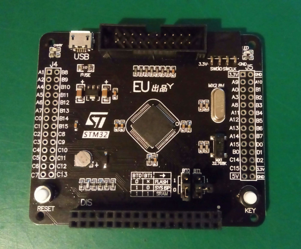
Instead I went with a STM32 ARM. The STM32F103RCT6 to be exact, this chip has a number of features that come in really useful.
| MSP430G2553 | ATMEGA328 | STM32F103RCT6 | |
| Bus Width | 16bit | 8bit | 32bit |
| Clock | 16MHz | 16MHz | 72MHz |
| SRAM | 512B | 2KB | 48KB |
| Flash | 16KB | 32KB | 256KB |
Just looking at the basics you can see the STM32 is leagues ahead. But that’s not all. The STM32 has 2 12bit DAC channels so we can generate the analogue voltages rather than having to have a separate DAC or R2R ladder reducing the component count on the final PCB.
Another advantage, we’ll be using a micro SD card to store the audio data, the MSP and ATMEGA generally use a serial peripheral in SPI mode to transfer data. Both have a maximum speed of 8MHz transferring 1 bit per cycle.
The STM32 has an SDIO peripheral designed specifically to talk to SD card, this reduces the programming complexity and allows for transferring 4 bits at a time at 10’s of MHz. Add to the mix DMA (Direct Memory Access) and the SDIO peripheral can happily transfer blocks of data to SRAM largely by itself leaving the ARM core plenty of time for other activities.
Other bits of hardware
In addition of the microcontroller we need some other bits to make it work.
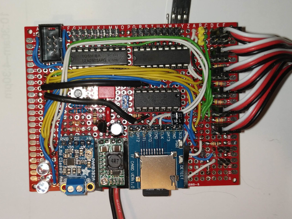
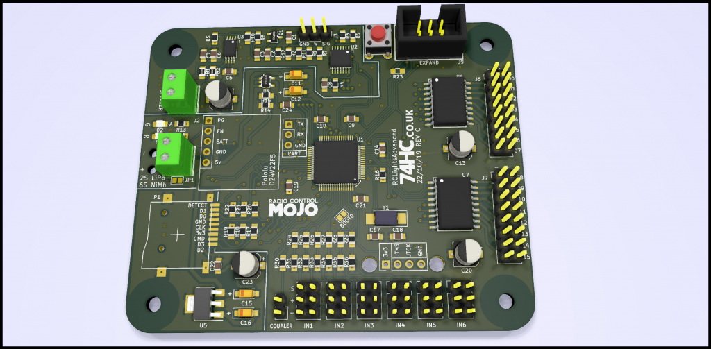
Starting at the top left of the image we’ve got a 6 pin box header, this is compatible with the expansion port on the smaller light controller boards. It’s handy for debugging as it squirts out the states of all the lights and the position of the inputs, for the model builder it’s handy for connecting the wireless trailer addon. The plan is to open the protocol and write a little library so anyone with some programming knowledge can use an Arduino to make their own addons.
Next are the good old reliable ULN2003A’s, these are darlington arrays, sets of transistors for switching the load of the connected LEDs. They’re old chips but they’re adequate for the job and readily available.
Toshiba do the TBD62083APG which is pin compatible and uses FETs, it would be a better choice and an easy swap, but they’re not quite so easy to get hold of.
There’s 2 chips on the board for a total of 16 LED channels, 14 of them are driven from a PWM channel on the STM32 for brightness control, 2 of them are ON/OFF only. Because we’ve got a microcontroller with lots of free time on it’s hands we don’t need to take shortcuts, so all 16 of the outputs can be freely configured for any function, brake lights, indicators and so on. Very handy for simplifying the truck wiring.
On the right side of the board we have the 6 inputs. These connect through to the RC receiver and monitor the pulsewidths. They tie to functions such as throttle, steering and lighting mode. Just like the lights any of the 6 inputs can be configured for any function.
Right in the middle of the board we have a 2 channel digital pot. This is a bit of a odd one, but bare with me.
As sounds are manipulated we want to dynamically change the volume such as the engine getting louder. Some sounds like the horn we just want to be able to adjust so it’s not too loud. We could do this in software, but remember we only have 12 bit DACs, so reducing the volume will also reduce the sound quality.
Instead we always use the DACs to they’re full getting the most from them, then we reduce the volume at the analogue stage keeping the sound quality.
At the bottom left we have a PAM8302 Class D amp. The bit we’re interested in is the little 8 pin IC. It can manage 2.5W into a 4ohm speaker which is plenty for the 1:14th trucks. It’s good enough with a small 40mm speaker, but using an 80mm speaker with an enclosure gets well into the annoying sound levels.
Bottom middle is a 5v switch mode supply. Because the sound system needs quite a lot of power we can’t run this board from the receiver power.
In the picture I was trying a very cheap Chinese boards but I found the IC lit up like a torch ever so easily. I’ve now changed to a different supply, but it still output the same 5v to run the amplifier and the LED outputs.
The input range is 5.5v to 40v so it’ll happily run from a very wide range of supplies, the typical 2S LiPo or 6S NiMh are well within it’s comfort zone.
The last widget at the bottom right is a micro SD socket. We’ve already mentioned it above, but to elaborate a little. It’ll let us access a huge amount of data, I’ve tried 32GB cards with no issues and there’s no reason you couldn’t use bigger ones.
On the card we use WAV files for the sounds, 16bit 44.1KHz to be exact, for all intents and purposes CD quality. You can also use lower sample rates to save card space but with large cards being so cheap these days it shouldn’t be an issue.
Along with the WAV files there’s also a config.txt that’s used to configure the user configurable settings, the card is formatted FAT32 so it’s as simple as popping the card into a SD reader on a laptop or perhaps even a phone and editing the text.
Also on the board there’s a couple of status LEDs that blink away when needed, most error messages come though the sound system as voice samples, but if it can’t play the sounds the LEDs become a fallback.
Advanced Prototype
Now we’ve got the rats nest on a perf board up and running and enough firmware to prove it’s all feasible, the next step is to design and assemble an advanced prototype.
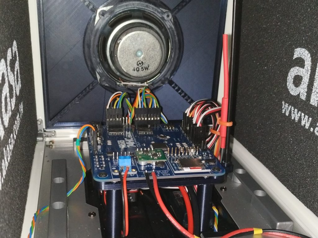
We’re still using the SD and amplifier modules since they’re perfectly serviceable, but this time all the rest of the components are on a single 2 layer PCB. This means ground and signals are routed in a somewhat better thought out layout. We can test the SD card at full speed and get a better idea about the level of decoupling we need to keep EMI down and to try and keep the analogue audio as clean as we can.
So far the advanced prototype boards have been running in a Tamiya 1850l box truck and a Tamiya MAN TGX. The firmware has seen lots of changes as it’s only running the boards you start to see what doesn’t quite work and of course the odd bug pops up too. The general operation though has been pretty good, even in they’re current state they’re perfectly usable.
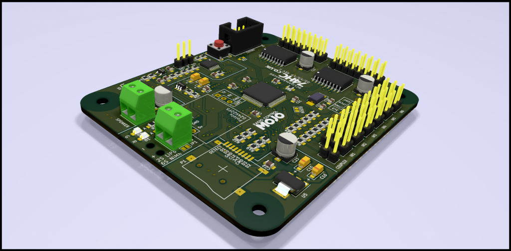
Very Advanced Prototype
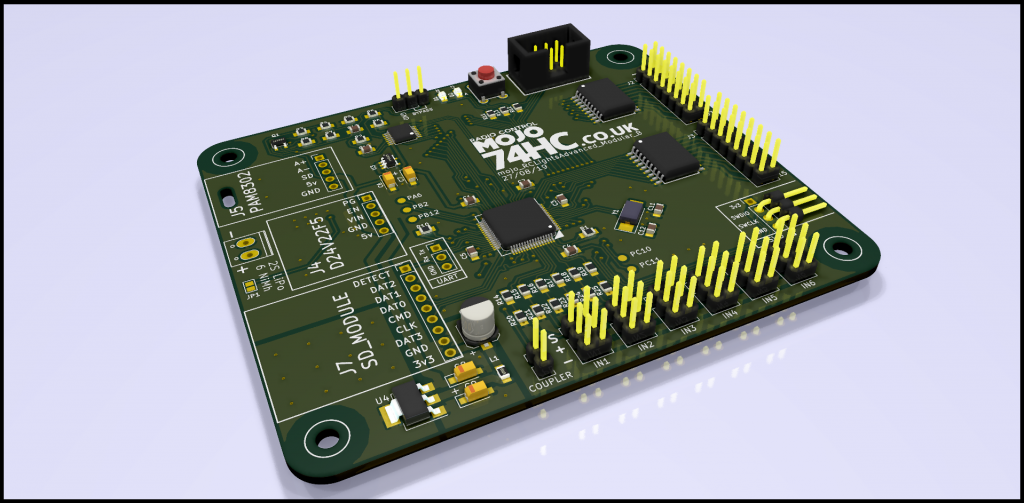
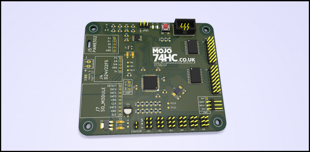
And here we are today. A lot was learned from the first PCB prototype, a number of minor features were found to be an easy addition and more bulk decoupling has been added, also the SD and amplifier modules have been swapped out in favour of using the components instead.
These are just renders from Kicad as the boards are still in the post, it’s around 30% smaller so should fits a little easier in the smaller truck cabs.

That’s about it for the time being, there’s still lots to do with perhaps one more PCB revision depending how this one goes and of course there’s all quite a list of lighting modes and effects to implement as well as sound effects, needless to say there’s a long list.
If you’re read though this and you’ve thought of a better name for the board leave a comment, names aren’t my strong point so any help would be great!